

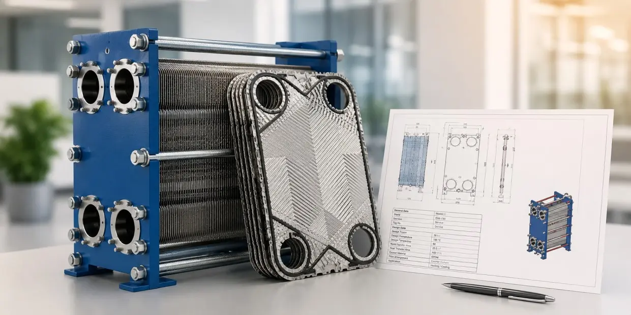
How to Size and Select a Plate Heat Exchanger
Sizing a plate heat exchanger takes five steps: calculate the heat load, calculate the log mean temperature difference, apply an overall heat transfer coefficient corrected for fouling, divide to get the required area, then divide again by the area per plate to get the plate count. The arithmetic is not difficult. The two places specifications go wrong are the fouling factor, where a shell and tube figure copied onto a plate datasheet will oversize the unit by 40 percent or more, and the allowable pressure drop, which decides the price of the unit and is usually left blank.
This guide runs a complete worked example in SI units, gives the reference values you need at each step, and sets out what to put on the enquiry so the quotes you get back are comparable.
The six inputs a vendor actually needs
You do not need to specify a size. You need to specify a duty, and there are six numbers that define one:
- Heat load, or enough information to calculate it
- Inlet and outlet temperature on the hot side
- Inlet and outlet temperature on the cold side
- Flow rate on both sides
- Maximum allowable pressure drop on both sides
- Maximum operating pressure and temperature
Anything beyond that is either derived or a preference. Anything less and the vendor is guessing, which is how two quotations for the same duty come back 30 percent apart on price.
Step 1: Heat load
Q = ṁ × cp × Δt
Where Q is heat load in kW, ṁ is mass flow in kg/s, cp is specific heat in kJ/kg·°C, and Δt is the temperature change on that side.
Run it on both sides and confirm the heat balance closes before going further. If the two sides disagree by more than a few percent, one of your four temperatures or two flows is wrong, and everything downstream will be wrong with it.
Worked example. A process water stream at 10 kg/s has to be cooled from 60°C to 40°C using cooling tower water available at 32°C.
Q = 10 × 4.18 × (60 − 40) = 836 kW
The cold side has to absorb the same 836 kW. At a cooling water flow of 12 kg/s:
Δt = 836 / (12 × 4.18) = 16.7°C
So the cooling water leaves at 32 + 16.7 = 48.7°C.
Check the flow ratio while you are here. A single pass plate exchanger works best when the two flows are within a ratio of roughly 0.7 to 1.4. Ours is 10 / 12 = 0.83, comfortably inside. Outside that band you need multiple passes or asymmetric plates, and a buyer who does not know this ends up with a badly matched single pass unit.
Step 2: Log mean temperature difference
LMTD = (ΔT₁ − ΔT₂) / ln(ΔT₁ / ΔT₂)
For counter-current flow, ΔT₁ is the difference at one end and ΔT₂ at the other:
- ΔT₁ = hot inlet − cold outlet
- ΔT₂ = hot outlet − cold inlet
Worked example.
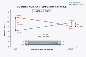
ΔT₁ = 60 − 48.7 = 11.3°C ΔT₂ = 40 − 32 = 8.0°C
LMTD = (11.3 − 8.0) / ln(11.3 / 8.0) = 3.3 / 0.3455 = 9.55°C
That is the effective driving force across the whole unit. Note how small it is. A 9.55°C driving force on a duty with a 60°C hot inlet is exactly the kind of close approach a plate exchanger is bought for, and it is where the technology earns its cost.
Step 3: The correction factor, and why it barely matters here
Shell and tube designs need an LMTD correction factor F, often 0.8 or lower, because multi-pass shell side flow is partly co-current. Plate exchangers are different.
Where both fluids take the same number of passes in true counter-current flow, F is typically above 0.95 and is often taken as 1.0. That is the structural reason a plate unit achieves a close approach and can handle a temperature cross, where the hot stream leaves colder than the cold stream leaves.
Unequal passes, for instance two passes on one side against one on the other, introduce co-current sections and F falls. There is no published F chart validated for plate geometry, so an unequal pass arrangement has to be rated in the vendor’s software rather than corrected by hand. Do not borrow a shell and tube F chart for this.
For our example, single pass both sides, F = 1.0.
Step 4: The overall heat transfer coefficient
A = Q / (U × F × LMTD)
Everything turns on U, and U is where published guidance disagrees most.
Clean coefficients
For a plate exchanger on clean water to water duty, published manufacturer figures sit at 6,000 to 7,500 W/m²·K. Another manufacturer source gives 800 to 1,200 Btu/hr·ft²·°F, which is 4,540 to 6,810 W/m²·K, and up to 1,400 to 1,500 Btu on aggressive plate patterns, which is 7,950 to 8,520 W/m²·K.
For comparison, a clean shell and tube unit on the same duty gives 2,000 to 2,500 W/m²·K.
Service coefficients
You will also see plate exchangers quoted at 1,000 to 4,000 W/m²·K for liquid to liquid duty. That is not a contradiction. The manufacturer figures are clean coefficients for water. The lower band spans all liquids including viscous ones and is closer to a fouled service value. Treat them as two different quantities and be clear which one you are using.
Two duty-specific figures worth having:
| Duty | Overall U |
| Sea water to fresh water, plate | 3,410 to 4,540 W/m²·K |
| Steam heating, plate, at 4.5 psi allowable drop | 4,370 W/m²·K |
| Gas cooling, plate | around 300 W/m²·K |
On oils and glycols: published plate-specific coefficients for water to oil and glycol duties could not be verified from an authoritative source. The oil figures that circulate widely, 350 to 700 W/m²·K for light oils and 60 to 300 for heavy oils, are shell and tube values. Do not carry them onto a plate design. Get those from a vendor rating run.
Correcting for fouling
1/U = 1/U_clean + Rf
The next section is about what Rf to use, and it is the most consequential decision in the whole calculation.
Fouling factors: the mistake that oversizes plate exchangers
Do not use TEMA fouling factors on a plate heat exchanger. This is not a matter of preference.
The Heat Exchange Institute states it directly in its technical sheet on plate heat exchanger fouling: “It is important not to use typical TEMA fouling factors for PHE designs. The TEMA fouling factors are not applicable to PHE’s and can result in excessive surface areas and poor PHE designs.”
Why plate exchangers foul less
The reason is shear stress. The same institute: “For the typical plate geometries with a relatively short channel flow length, PHE’s can generate shear stresses generally five times higher than those generated in an equivalent shell and tube heat exchanger.”
Corrugated channels keep the flow turbulent at very low velocity and scour the surface continuously. A plate exchanger is partly self-cleaning in a way a shell is not.
How much less
Testing reported by APV against HTRI data put numbers on it. TEMA recommends 0.002 hr·ft²·°F/Btu for the water system tested. The maximum fouling resistance actually measured in the plate exchanger was less than 0.0005, only 25 percent of the TEMA recommendation.
HTRI’s own guidance arrives independently at the same place: use approximately 25 percent of the corresponding shell and tube value.
Plate-specific fouling factors
| Fluid | Rf (m²·K/W) |
| Water, demineralized or distilled | 0.88 × 10⁻⁵ |
| Water, soft | 1.76 × 10⁻⁵ |
| Cooling tower, treated | 3.52 × 10⁻⁵ |
| Water, hard | 4.40 × 10⁻⁵ |
| Sea water, ocean | 2.64 × 10⁻⁵ |
| Sea water, coastal or estuary | 4.40 × 10⁻⁵ |
| River or canal water | 4.40 × 10⁻⁵ |
| Engine jacket water | 5.28 × 10⁻⁵ |
| Lubricating oils | 1.76 to 4.40 × 10⁻⁵ |
| Vegetable oils | 1.76 to 5.28 × 10⁻⁵ |
| Organic solvents | 0.88 to 2.64 × 10⁻⁵ |
| Steam | 0.88 × 10⁻⁵ |
A cross-check worth seeing. A separate manufacturer source, working entirely in SI and never citing the table above, states that a typical shell and tube Rf is 1 × 10⁻⁴ m²·K/W, and that to achieve a 20 to 25 percent margin in a plate unit at 6,000 to 7,500 W/m²·K the Rf should only be 0.33 × 10⁻⁴.
That is 3.3 × 10⁻⁵, sitting on the cooling tower row. Two independent sources in different unit systems landing on the same number is about as good as corroboration gets in this field.
The cost of getting it wrong
One published estimate puts it plainly: carrying the traditional 0.0005 fouling factor across “will cause 30 to 40 percent increase of the effective heat transfer area.”
Worked example. Cooling tower water on one side, clean process water on the other. Take Rf = 3.52 × 10⁻⁵ and a clean coefficient of 6,000 W/m²·K.
1/U = 1/6000 + 3.52 × 10⁻⁵ = 1.667 × 10⁻⁴ + 0.352 × 10⁻⁴ = 2.019 × 10⁻⁴
U = 4,953 W/m²·K
Now the area:
A = 836,000 / (4,953 × 1.0 × 9.55) = 17.7 m²
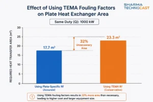
Had we used the TEMA figure of 1 × 10⁻⁴ instead, U would fall to 3,750 W/m²·K and the required area would rise to 23.3 m². That is 32 percent more plates for the same duty, bought on a number that does not apply to the geometry.
Step 5: Plate count
N = A / A_plate, with channels per side n = (N − 1) / 2
Effective heat transfer area per plate runs from about 0.03 m² to 3.5 m² depending on frame size. A single frame holds up to 600 or 700 plates, giving total surface above 2,400 m².
Two corrections most guides miss.
The two end plates transfer no heat. Effective area is (N − 2) × A_plate, not N × A_plate. On a small pack that matters.
Plate area is the developed area, not the outline. The pressed corrugation makes the actual surface larger than the flat projection, by a factor known as the enlargement factor. One published example gives 1.81 ft² developed against 1.45 ft² projected, a ratio of about 1.25. If you calculate plate area from outline dimensions you will over-count by 15 to 25 percent and under-order plates.
Worked example. On a medium frame with 0.5 m² per plate:
Plates required = 17.7 / 0.5 = 35.4 effective
Adding the two end plates and rounding to an odd total gives 39 plates, of which 37 transfer heat, providing 18.5 m² against the 17.7 m² required. Channels per side = (39 − 1) / 2 = 19.
That is a 4.5 percent surplus on area, which is the right kind of rounding. The next section explains why more would be worse.
How much design margin, and why more is worse
Design margin in a plate exchanger is not a free safety factor. It is a decision with a cost that runs in the wrong direction.
The relationship
M = U_clean × Rf
Margin equals the clean coefficient multiplied by the fouling factor. Check it against our numbers: 6,000 × 3.52 × 10⁻⁵ = 0.211, a 21 percent margin, already built into the sizing above through the fouling factor. You do not then add more on top.
The consequence that matters: because a plate exchanger’s clean coefficient is roughly three times a shell and tube’s, the same fouling factor buys three times the margin. Copying a shell and tube Rf onto a plate datasheet does not give you a 20 percent margin. It gives you 60 to 75 percent.
Published guidance
| Source | Recommended margin |
| Plate manufacturer, water to water | 0 to 15 percent depending on water quality |
| APV, by fouling severity | 5 percent low, 10 percent moderate, 15 to 20 percent high |
| Heat Exchange Institute, power plant | 5 to 10 percent nominal |
| API 662 Annex A | minimum 10 percent, up to 25 percent for crude oil service |
| Practicing engineers, general | 5 to 10 percent overdesign is common |
These disagree, and the disagreement is mostly about service severity rather than method. Take the low end for clean closed loops and the high end for dirty open water.
Why margin is self-defeating in a plate exchanger
This is the part that does not appear in most sizing guides, and it is the most useful thing in this one.
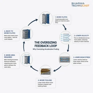
Extra plates go in parallel. Parallel channels split the flow. Lower flow per channel means lower velocity, lower turbulence, lower shear stress, and therefore faster fouling. You added area to guard against fouling and the added area caused fouling.
One manufacturer handbook states the mechanism directly: specifying a high fouling resistance means extra plates, “which results in lower velocities, more extreme temperatures during startup, and the probability of higher fouling rates.” Practicing engineers put it more bluntly: heat exchangers that are too oversized are always going to underperform.
It is a positive feedback loop, and it is why a plate exchanger cannot be made safer by simply buying more of it.
What to do instead: buy frame, not plates
Size the plate pack tight, and specify a frame with room to grow.
A major operator specification requires that the “plate type heat exchanger shall be designed (frame, tightening bolts and supports) for a future installation of 20 percent additional plates.” Institute guidance for power plant duty goes further, at frame extension capacities of 30 to 50 percent.
This costs very little at purchase, it does not degrade performance on day one, and it means a genuine capacity increase later is a plate order rather than a new unit.
Theta, thermal length, and which plate you are actually being sold
Θ = δt / LMTD
Theta, also called thermal length, describes how hard a duty is thermally. It is the temperature change achieved divided by the driving force available.
Theta is the same number as NTU for that side. Since Q = ṁ·cp·δt = U·A·LMTD, it follows that δt/LMTD = UA/(ṁ·cp), which is the definition of NTU. Worth knowing because vendors use both words for the same quantity.
Worked example. Our hot side: δt = 20°C, LMTD = 9.55°C, so Θ = 2.09. A moderately demanding duty.
Ranges, and a genuine disagreement in the literature
Published figures do not agree and should not be blended:
- One manufacturer states shell and tube units reach a maximum theta around 1, while plate units reach theta of 10 and more
- CIBSE guidance calls a high theta 3 or above and a low theta close to 1
- Process engineering literature classifies low-NTU plates as below 1 and high-NTU plates as above 1
These are reconcilable if you read them as per-plate theta, roughly 0.5 to 1 for a low theta plate and 2 to 4 for a high theta plate, against total duty theta achievable by multi-passing the whole unit. No source states that reconciliation explicitly, so treat each figure with its own definition rather than averaging them.
How theta decides the plate
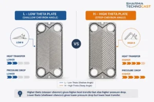
Plates come in low theta and high theta patterns, and the difference is the chevron angle pressed into them.
| Low theta (L) plate | High theta (H) plate | |
| Chevron angle | Smaller | Larger |
| Heat transfer | Less | More |
| Pressure drop | Lower | Higher |
| Flow resistance | Lower | Higher |
Experimental work confirms the direction. At an aspect ratio of 1.33 and Reynolds number 2,500, the Nusselt number at a 60 degree chevron angle is twice that at 30 degrees, and higher chevron angles give 1.3 to 2.06 times higher Nusselt numbers across the range.
Note that at least one widely circulated industry article states this relationship backwards. If a source tells you a larger chevron angle gives less heat transfer, it is wrong and it is internally inconsistent elsewhere too.
Mixing plate types in one pack is standard practice. Combining L and H plates produces intermediate channels, and asymmetric packs exist for duties where the two sides have very different flow rates. Ask which plate you are being quoted. It tells you whether the pressure drop figure on the quotation is honest.
Channel velocity and the 50 Pa rule
| Parameter | Value |
| Channel velocity, water-like fluids, turbulent | 0.3 to 0.9 m/s |
| Channel velocity, wider range across fluids | 0.1 to 1.0 m/s |
| Port velocity, design basis | up to 6.1 m/s |
| Port velocity, absolute maximum | 7.6 m/s |
| Turbulence onset, brazed plate | Reynolds number around 150 |
| Turbulence onset, plain tube | Reynolds number around 2,300 |
The velocity figures are worth having, but the number that actually governs fouling is wall shear stress, not velocity.
Published guidance puts the self-cleaning threshold at 50 Pa: “As a numerical limit value, 50 Pa would be enough to design a heat exchanger able to self-clean with the sweeping caused by the high shear stress on wall,” with a minimum of at least 30 Pa for more viscous fluids. Process engineering literature independently gives the same 50 Pa figure as the minimum below which frequent fouling should be expected.
Two independent sources converging on the same threshold makes this a usable design check.
Ask for wall shear stress in the rating output. If it comes back below 30 to 50 Pa, you have bought a fouling problem regardless of how much area is in the unit. This single question does more to protect a plate exchanger specification than any fouling factor.
Allowable pressure drop and where it gets spent
| Duty | Allowable pressure drop |
| Water to water | 20 to 100 kPa is accepted as normal |
| Gas cooling | around 3.5 kPa |
| Condensing duty | often below 7 kPa |
| Maximum differential across the plate pack | 5 bar for standard liquid to liquid units |
State a number. A plate exchanger quoted against an unstated allowable pressure drop will be designed at whatever value flatters the price, and two quotations designed at different pressure drops are not comparable documents.
Where the pressure drop goes
This is the sophisticated part of a plate specification and almost nobody asks about it.
Pressure drop spent in the ports buys no heat transfer. It is pure loss. In a well designed unit the port pressure drop should be around 10 percent of the total, and can reach 25 percent on a single pass exchanger before it becomes a problem.
The same rule stated from the owner’s side appears in operator specifications: the pressure drop developed at the plate surface shall be at least 75 percent of the total for each fluid.
A related check on maldistribution: nozzle pressure drop should stay at or below 40 percent of the total exchanger pressure drop, or flow distributes unevenly across the pack and some of the area you paid for does nothing.
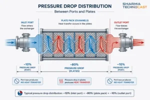
Ask what fraction of the quoted pressure drop is in the ports. If the vendor cannot tell you, they have not rated it properly.
Sizing for Indian cooling water
Most published sizing guidance assumes European or North American water quality. Indian open recirculating cooling systems operate to different limits, and the difference changes the margin you need.
IS 8188:1999, Treatment of Water for Cooling Towers, sets the recommended quality for recirculating cooling water:
| Parameter | IS 8188 limit |
| Turbidity | not greater than 50 NTU |
| Total hardness | not greater than 250 ppm as CaCO₃ |
| Temporary hardness | not greater than 200 ppm as CaCO₃ |
| Total dissolved solids | not greater than 500 ppm |
| Sulphate | not greater than 600 ppm |
| Silica | not greater than 75 ppm |
| Iron plus manganese | not greater than 0.5 ppm |
| Residual chlorine | 0.2 to 0.5 ppm |
| pH | to suit Langelier index around +0.2 |
The standard also caps cycles of concentration against make-up water hardness: 2.0 cycles at 100 ppm CaCO₃, falling to 1.1 cycles at 300 ppm.
What this means for sizing. IS 8188 permits turbidity to 50 NTU and total hardness to 250 ppm. At those permitted limits the water sits on the hard water row of the fouling table, Rf = 4.40 × 10⁻⁵ m²·K/W. Against a clean coefficient of 6,000 W/m²·K that implies a design margin of:
M = 6,000 × 4.40 × 10⁻⁵ = 26 percent
That is meaningfully more than the 0 to 15 percent that manufacturer guidance suggests for water to water duty, and the gap is explained entirely by water quality. A plate exchanger sized on European assumptions and installed on Indian cooling tower water at the permitted limits will be short of surface.
What to specify:
- Get an actual water analysis rather than assuming compliance with IS 8188. The standard sets what is recommended, not what is in your basin.
- A strainer ahead of the unit is not optional on open cooling water, and the mesh has to be selected against the channel gap rather than by habit.
- For river or canal intake, particularly through monsoon, wide gap plates exist specifically for fluids carrying fibres and coarse particles. Manufacturers publish no universal particle size limit, so this has to be sized against your own analysis.
A note on honesty: no published field data on monsoon silt loading and plate exchanger fouling in Indian conditions could be found for this guide. The argument above is built from what IS 8188 permits and what the published fouling table implies, not from measured Indian plant data.
Steam duty and Indian boiler regulation
If either side of the exchanger is steam, one statutory question has to be settled at design stage rather than at inspection.
The trigger for Indian boiler regulation is steam being generated in the vessel, not steam being present. The covered equipment wording extends to heat exchangers, converters, evaporators and similar vessels in which steam is generated. A reboiler, vaporizer or waste heat boiler is in scope. A plate exchanger heated by steam on one side generally is not, although its steam pipe connections may qualify as regulated items in their own right.
Note also that the legislative basis changed recently. The Boilers Act 2025 came into force on 1 May 2025 and repealed the Boilers Act 1923. A draft of revised Indian Boiler Regulations was issued for comment in January 2026 and, as at the date of this article, had not been confirmed as notified.
For a gasketed plate unit the practical steam ceiling is around 10 bar and 180°C depending on gasket compound, well below what the frame is rated for.
How to specify so you get the right unit
A checklist, drawn from everything above.
Give the six inputs, not a size. Heat load, four temperatures, two flows, two allowable pressure drops, maximum operating pressure and temperature.
State the allowable pressure drop in kPa on both sides. Without it the quotations are not comparable.
Never put a TEMA fouling factor on a plate enquiry. State a margin as a percentage, or state a plate-specific Rf from the table above.
Ask for the wall shear stress or channel velocity in the rating output. Below 30 to 50 Pa is a fouling problem waiting to happen.
Ask what fraction of the pressure drop is in the ports. Around 10 percent, 25 percent at worst.
Ask which plate type has been selected, L, M or H. It reveals whether the pressure drop quoted is realistic.
Check the flow ratio. Between 0.7 and 1.4 for a single pass unit. Outside that, expect multi-pass or asymmetric plates.
Specify frame capacity for future plates, 20 to 30 percent, rather than buying surplus plates now.
Provide a real water analysis for open cooling water duty rather than assuming a standard.
Consider not declaring your safety factor. Experienced specifiers add margin to the stated duty rather than announcing it, because a declared margin gets stacked on top of the vendor’s own and the unit ends up 60 percent oversurfaced.
Frequently asked questions
How do you calculate the size of a plate heat exchanger?
Calculate the heat load from Q = ṁ × cp × Δt, calculate the log mean temperature difference from the four terminal temperatures, correct the overall heat transfer coefficient for fouling using 1/U = 1/U_clean + Rf, then find the required area from A = Q / (U × F × LMTD). Divide the area by the effective area per plate to get the plate count, remembering that the two end plates transfer no heat.
What U value should I use for a plate heat exchanger?
For clean water to water duty, published manufacturer figures are 6,000 to 7,500 W/m²·K, against 2,000 to 2,500 W/m²·K for a shell and tube unit on the same duty. Lower published bands of 1,000 to 4,000 W/m²·K are service values that include fouling and cover a wider range of liquids. Be clear which one you are using, and do not carry shell and tube coefficients for oils onto a plate design.
Can I use TEMA fouling factors for a plate heat exchanger?
No. The Heat Exchange Institute states that TEMA fouling factors are not applicable to plate heat exchangers and can result in excessive surface areas and poor designs. Corrugated plate channels generate roughly five times the wall shear stress of an equivalent shell and tube unit, so measured fouling resistance runs at about 25 percent of the TEMA figure. Applying the shell and tube value typically adds 30 to 40 percent unnecessary area.
How much design margin should a plate heat exchanger have?
Margin equals the clean coefficient multiplied by the fouling factor, so it is already built in once you apply a realistic Rf. Manufacturer guidance suggests 0 to 15 percent for water to water depending on water quality, industry guidance 5 to 20 percent by fouling severity, and API 662 a minimum of 10 percent rising to 25 percent for crude oil service. Adding more is counterproductive, because extra plates lower channel velocity, which lowers shear stress and accelerates fouling.
What is theta or thermal length in a plate heat exchanger?
Theta is the temperature change divided by the log mean temperature difference, and it is the same quantity as NTU for that side. It measures how thermally demanding a duty is and determines whether you need a low theta plate with a shallow chevron angle and low pressure drop, or a high theta plate with a steeper angle, more heat transfer and higher pressure drop.
What pressure drop should I specify for a plate heat exchanger?
For water to water duty, 20 to 100 kPa is accepted as normal. State a figure, because a unit quoted against an unstated pressure drop will be designed at whatever value produces the lowest price, and quotations designed at different pressure drops cannot be compared. Also ask what proportion of that drop occurs in the ports, since port pressure drop produces no heat transfer and should be around 10 percent of the total.
Sharma Technocast manufactures heat exchangers and heat exchanger components from our works in Ahmedabad, working to customer drawings and specifications under ISO 9001 and AS9100. If you have a duty to size, our team can work through the selection with you. Our guide to the plate heat exchanger covers construction in more detail, the comparison of plate against shell and tube covers choosing between the two types, and our heat exchanger manufacturing process guide covers how these units are built and tested.