

Plate Heat Exchanger vs Shell and Tube Heat Exchanger: A Specification Guide
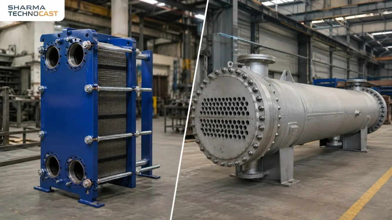
A plate heat exchanger transfers heat between thin corrugated plates clamped in a frame. A shell and tube heat exchanger passes one fluid through a tube bundle and the other around it inside a shell. Plate units reach three to five times the heat transfer coefficient in a third to a fifth of the footprint and can close to a 1°C approach. Shell and tube handles pressures above 100 bar, temperatures above 600°C, and fluids carrying particulates that would block a plate channel.
That much is settled and you will find it on every page that covers this topic. What you will not find is agreement on pressure drop, an honest account of what each type costs to own, or a codes section written against Indian law as it stands in 2026. This guide covers those.
Plate heat exchanger vs shell and tube: the short answer
Specify a plate heat exchanger when the approach temperature is below about 5°C, when the duty involves a temperature cross, when floor space is restricted, or when the fluids are clean and the capacity may need to grow.
Specify a shell and tube heat exchanger when pressure exceeds roughly 30 bar, when temperature exceeds roughly 200°C, when the fluid carries particulates or fibers, when the duty involves a phase change, or when the project specification calls up TEMA and no alternative acceptance basis has been agreed.
Everything below is the reasoning behind those two lists, and the places where the published comparisons get it wrong.
How a plate heat exchanger and a shell and tube heat exchanger work
A plate heat exchanger stacks pressed corrugated plates in a frame, with gaskets sealing between them so that alternate channels carry the hot and cold streams. Tie bars clamp the pack together. The corrugation is the whole point: the pressed chevron pattern forces the flow to cross ridges rather than run straight, which produces turbulence at very low velocity.
A shell and tube heat exchanger is built like a pressure vessel. One fluid runs through a bundle of tubes, the other passes through the shell around them, and baffles direct the shell side flow across the bundle rather than along it.
The difference that matters is physical scale. Plates are typically 0.4 to 0.6 mm thick with channel gaps of 2 to 5 mm. Tube walls run 1.5 to 3 mm with bores of 15 to 25 mm. The hydraulic diameter of a plate channel is roughly 4 to 8 mm against 15 to 25 mm in a tube.
Everything downstream follows from that. Thin plates and narrow channels give exceptional heat transfer, low fluid inventory, and very little tolerance for pressure, particulates or thermal shock. Thick tubes and open shells give the opposite. Neither is an improvement on the other. They occupy different parts of the design space.
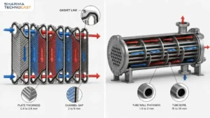
Plate heat exchanger vs shell and tube comparison table
| Shell and tube | Gasketed plate | Brazed plate | |
|---|---|---|---|
| Overall U, water to water | 800 to 2,000 W/m²K | 3,000 to 7,000 W/m²K | 3,000 to 7,000 W/m²K |
| Minimum approach temperature | around 5°C | around 1°C | around 1°C |
| Maximum pressure | 100 to 300 bar shell side, higher tube side | 25 to 30 bar | 45 to 65 bar |
| Maximum temperature | 600°C and above with alloy steel | 180 to 200°C, gasket limited | −195 to +225°C |
| Passage size | Tube bore 15 to 25 mm | Channel gap 2 to 5 mm | Channel gap 2 to 5 mm |
| Wall thickness | Tube wall 1.5 to 3 mm | Plate 0.4 to 0.6 mm | Plate 0.4 to 0.6 mm |
| Maximum heat transfer area | Effectively unlimited | Up to about 4,000 m² | Up to about 50 m² |
| Footprint for the same duty | Baseline | One third to one fifth | Smaller again |
| Fouling tolerance | High, passes particulates and slurries | Low, particles above 0.5 mm bridge the channel | Low, and cannot be opened |
| Cleaning | Mechanical or chemical, bundle can be pulled | Open the frame, clean each plate | Chemical only |
| Capacity change | Requires a new unit | Add plates to the frame | Fixed, replace the unit |
| Viscosity ceiling | High | Around 5,000 cP in practice | Similar |
| Governing standards | TEMA, IS 4503, ASME VIII | ASME VIII, PED, EN 13445, AHRI 400 | Same |
One caveat on the U values. Published sources disagree by roughly a factor of two on shell and tube. Some quote 150 to 1,200 W/m²K, others 800 to 2,000. Both are defensible, because the overall coefficient depends on the duty, the fluid velocities and the fouling allowance rather than on the exchanger type. Treat any single number quoted at you as the opening of a calculation, not a specification.
Which is more efficient, a plate or shell and tube heat exchanger?
A plate heat exchanger achieves a higher overall heat transfer coefficient than a shell and tube unit on the same liquid to liquid duty, typically by a factor of three to five. Two things cause it.
The corrugated channel goes turbulent at a Reynolds number somewhere between 10 and 400, where a plain tube needs roughly 2,300. And the hydraulic diameter is three to five times smaller, which raises the film coefficient for free, since the coefficient scales inversely with hydraulic diameter. A plate unit reaches 3,000 to 7,000 W/m²K at channel velocities of 0.3 to 0.9 m/s. A tube typically needs 1 to 3 m/s to reach a fraction of that.
The shell side compounds the gap. Baffled cross flow leaks around the bundle, bypasses between the bundle and the shell, and leaves low velocity dead zones behind the baffles. It is not a thermally efficient geometry and it was never intended to be. It is a forgiving one.
Approach temperature is the real decision, not efficiency
A single pass plate heat exchanger is true counter current and can close to a 1°C approach. A multi pass shell and tube exchanger is partly co-current and stops converging below roughly 5°C.
This decides more selections than efficiency claims do, and most comparisons reduce it to “more efficient” and move on. Because the two streams run in genuine opposition along the full plate length, a plate unit also handles a temperature cross, where the cold stream leaves hotter than the hot stream leaves. A multi pass shell and tube cannot do this at all. You can force it by putting shells in series, at which point the cost and space advantage of the tubular unit has gone.
If you are recovering waste heat, or squeezing the last few degrees out of a cooling duty, the approach requirement picks the type before cost enters the conversation.
Does a plate heat exchanger have higher pressure drop than shell and tube?
This is where the published comparisons fall apart, and it is worth setting out properly because a buyer reading the search results will get both answers.
Some manufacturer pages state that a plate heat exchanger has substantially lower pressure drop than a tubular unit designed to the same specification. Others state the opposite, that the open geometry of a shell and tube unit minimizes pressure drop and lets the end user run smaller pumps. Engineers on technical forums report that plate units cost more in pumping power over their life. All of these are published as flat statements of fact. None of them says on what basis the comparison was made, and that omission is the entire problem.
Pressure drop is a design input, not a property of the geometry
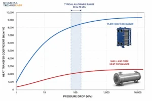
Neither exchanger has an inherent pressure drop. The specifier states an allowable figure and both vendors design to hit it.
The customary allowable for a liquid duty is roughly 50 to 70 kPa per unit, and it is close to identical for both types. The standard shell and tube design references put it at 0.5 to 0.7 kg/cm² per shell, which is 49 to 69 kPa. Plate manufacturer design guidance gives 50 to 70 kPa for a cooling pressure breaker and 80 to 100 kPa for cooling tower or sea water duty. The ranges overlap almost exactly.
So the question “which has higher pressure drop” is malformed as usually asked. The useful question is what each geometry gives you in return for the pressure you spend.
The exchange rate is the same, the curve is not
In both geometries, heat transfer rises roughly as the cube root of pressure drop. For a corrugated plate channel, Martin’s correlation gives the Nusselt number as proportional to the Hagen number raised to 0.374, which makes pressure drop scale as the heat transfer coefficient to roughly the power 2.7. For tube side flow the standard design correlations give the coefficient as proportional to pressure drop to the power 0.40. Those are close enough to call the same law.
What differs is the constant. The plate channel sits on a higher curve: it returns more heat transfer for every unit of pressure spent, for the two geometric reasons given earlier. And that is exactly why plate units end up with higher absolute pressure drop in service. Designers do not bank the advantage as a lower pressure drop. They spend it, because the plates are the expensive part and the pressure is comparatively cheap.
The data that settles it
A published cost optimization ran both exchanger types against the same water to water duty and let an algorithm find the least cost design for each.
| Shell and tube | Gasketed plate | |
|---|---|---|
| Heat transfer area | 260.9 m² | 52.6 m² |
| Pressure drop | 8.6 kPa shell, 29.7 kPa tube | 78.9 kPa hot, 21.4 kPa cold |
| Capital cost | $54,818 | $13,871 |
| Pumping cost per year | $56,412 | $82,721 |
| Total annualized cost | $111,230 | $96,592 |
The optimizer independently pushed the plate unit toward a small area, high pressure drop design and the tubular unit toward a large area, low pressure drop design. The plate unit’s pumping bill came out 47 percent higher. Its total cost came out 13 percent lower.
Both camps in the published argument are quoting different rows of the same table. The plate vendors quote total cost. The tube vendors quote pumping cost. Neither is lying and neither is telling you the whole thing.
What to do about it
State your allowable pressure drop, on both sides, in the enquiry. If you do not, the two vendors will quote on different bases and the comparison you eventually make will be meaningless. A plate quotation designed to 20 kPa and a tubular quotation designed to 60 kPa are not comparable documents, and nothing on either datasheet will tell you that.
What does a plate heat exchanger cost to own compared with shell and tube?
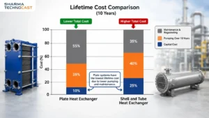
Capital cost is the number everyone compares and the one that matters least. A plate unit is usually cheaper to buy for the same duty, sometimes dramatically so, because it needs a fifth of the heat transfer area. Three other costs decide the outcome.
Pumping power over the life of the unit
Covered above. On cost optimized designs the plate unit generally runs the higher pumping bill. Whether that outweighs the capital saving depends on electricity tariff, running hours and duty.
One honest correction to how this is usually calculated. Life cycle pumping costs are almost always quoted at design flow, and that overstates the real figure considerably. Pressure drop falls with roughly the square of flow, so a unit designed for 50 kPa sees around 12.5 kPa at half flow. Industry guidance on HVAC duties notes that full load operation is typically in the region of eleven days a year. Any lifetime pumping argument quoted at design conditions, in either direction, should be discounted heavily.
Specifying a tighter pressure drop usually costs more, not less
This is counterintuitive and it is a common procurement error. Published manufacturer data for a 2,000 kW duty over five years:
| Design pressure drop | Equipment cost | Five year pumping | Five year maintenance | Five year total |
|---|---|---|---|---|
| 20 kPa | €49,277 | €32,497 | €13,551 | €95,325 |
| 50 kPa | €38,556 | €36,928 | €10,603 | €86,087 |
| 70 kPa | €34,810 | €39,883 | negligible | €74,693 |
Moving from 20 kPa to 70 kPa raised the pumping energy by 23 percent, cut the equipment cost by 29 percent, and removed the fouling driven maintenance entirely, because the higher shear keeps the plates clean. The tightest specification produced the most expensive installation by a wide margin.
Related point: fouling has a running cost of its own. In a district heating case from the same source, pump power rose from 10.0 kW to 14.0 kW over one year of fouling. That is a 40 percent energy penalty from pressure drop creep alone, and it works against low velocity designs of either type.
Regasketing
This is the cost that swings the comparison back toward shell and tube, and almost nothing published on the plate side mentions it.
A gasketed plate heat exchanger has a gasket on every plate. A large unit has hundreds. Replacing them is a scheduled shutdown, a full strip of the pack, and either adhesive bonding with a cure time or clip fitting depending on plate design. One operator on a technical forum put a single regasketing job at around $150,000, and observed that the figure would buy a new shell and tube unit outright.
A welded shell and tube exchanger has no internal gaskets at all. Where a removable bundle is used, the seal is an O ring at the tube sheet, which is cheap and quick.
Published gasket life figures vary so widely that you should not plan against any of them without asking your vendor directly. Sources give one to two years, three to five years, five to ten years, and five years between services. The spread is real, because life depends on operating temperature, thermal cycling, the process fluid, cleaning chemistry and clamping load. Take the figure from the manufacturer for your specific compound and duty, in writing.
Set against that, plate reliability in service can be very good. One operator reported two plate failures in seventeen years across seventy two units. The gaskets are the consumable, not the plates.
Which handles fouling better, plate or shell and tube?
Shell and tube tolerates fouling far better. Plate exchangers foul more slowly per unit of area, because corrugation keeps the flow turbulent and the shear high, but they block outright on particles above roughly 0.5 mm and on fibers of 1 to 5 mm, because the channel gap is only 2 to 5 mm.
That distinction matters more than the fouling rate. A shell and tube unit with partial fouling keeps running at reduced duty. A plate unit with a blocked channel stops.
Do not apply TEMA fouling factors to a plate heat exchanger
TEMA fouling allowances are written for shell and tube geometry and typically run five to ten times larger than a plate unit needs. Carry one into a plate design and three things happen. You oversize the unit and pay for plates you do not need. You end up running at lower channel velocity than intended. And the lower velocity causes the fouling you were guarding against in the first place.
This happens routinely, because a specification gets copied from a previous tubular enquiry and the fouling line goes across unchanged. It is worth checking before an enquiry goes out.
Indian cooling water
On open recirculating cooling water in Indian conditions, particularly through monsoon with high suspended solids and silt loading, the physical blockage limit matters more than any fouling coefficient. A strainer ahead of a plate exchanger is not optional, and the mesh needs to be selected against the channel gap rather than against habit.
Hard water is the other constraint. Scaling on a brazed unit cannot be dealt with mechanically, because the unit cannot be opened. It is chemical cleaning or replacement.
Pressure and temperature limits of plate and shell and tube heat exchangers
On a gasketed plate heat exchanger the gasket sets the temperature ceiling, not the plate. Stainless plate runs comfortably above 400°C. The elastomer sealing between plates gives up far below that.
Published limits for the same compound vary by 30 to 50°C between manufacturers, which is more variation than most datasheets admit. The ranges below reflect that spread rather than picking a single figure:
| Gasket material | Published temperature limits | Typical service |
|---|---|---|
| NBR (nitrile) | 110 to 160°C | Water, mineral oils, edible oils |
| EPDM | 150 to 200°C | Hot water, low pressure steam, alkalis |
| HNBR | around 165°C | Crude oil, steam, mining duty |
| FKM (Viton) | 170 to 200°C | Hot oils, concentrated acids |
| CR (chloroprene) | up to about 100°C | Moderate chemicals, oils |
Specify against your own operating conditions and get the figure confirmed for the compound you are buying. A datasheet best case and a continuous service rating are not the same number.
For steam, the practical ceiling on a gasketed unit is around 10 bar and 180°C, well below what the frame is rated for.
Shell and tube has no soft sealing constraint anywhere in the pressure envelope. Shell side pressures of 100 to 300 bar are routine, the tube side goes considerably higher, and temperature is limited by material selection rather than by a seal.
Plate is four different products, not one
Every comparison on this topic treats “plate” as a single thing. It is four, and the differences are large enough to change the answer.
| Gasketed | Brazed | Semi welded | Welded | |
|---|---|---|---|---|
| Maximum pressure | 25 to 30 bar | 45 to 65 bar | around 40 bar | around 100 bar |
| Maximum temperature | −25 to +180°C | −195 to +225°C | up to 200°C | up to 350°C |
| Maximum area | around 4,000 m² | around 50 m² | 1,000 m² | 1,000 m² |
| Can be opened | Yes | No | Gasketed side only | Limited |
| Expandable | Yes | No | No | No |
| Relative cost | 1.0x | 0.7 to 1.0x | 1.3 to 1.8x | 1.5 to 2.5x |
Two consequences follow.
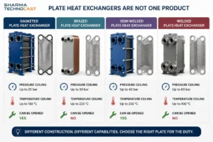
A welded plate exchanger at around 100 bar and 350°C removes a large part of the usual case for shell and tube. If the objection to plate was pressure or temperature rather than fouling, welded plate deserves consideration before the enquiry is written as tubular by default. The trade is that it cannot be opened, cannot be expanded, costs more, and comes from fewer suppliers.
Semi welded is the answer for ammonia refrigeration and for single aggressive stream duties. One side is welded, so the aggressive or refrigerant stream never touches a gasket, and the other side stays gasketed and serviceable. It appears on almost none of the published comparisons.
Brazed units are consumables. They cannot be opened, so they cannot be mechanically cleaned, regasketed or expanded. Copper brazing is also incompatible with ammonia, sea water and several process chemicals, which is what nickel brazed variants exist for. Specify the braze alloy against the fluid, not just the duty.
Which codes apply to plate and shell and tube heat exchangers in India?
This section is where most published guidance on Indian projects is out of date, including guidance published this year.
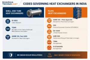
Shell and tube
IS 4503:1967, Shell and Tube Type Heat Exchangers. Its stated scope covers “the design, construction, inspection and testing of cylindrical shell and plain tube heat exchangers for application in the petroleum and general chemical industry.” Pressure classes are designated separately for shell and tube side in kgf/cm² gauge at 2.5, 6.3, 10, 16, 25 and 40. Basic metal temperatures are 250°C for carbon steel, 120°C for stainless and 65°C for non-ferrous.
The point buyers miss is in Clause 21.0, which states that the testing procedure “covers only the mechanical design and construction of the heat exchanger, and does not include the process performance.” IS 4503 will not tell you whether the unit makes its duty. Thermal rating sits entirely outside it.
It is also older than it looks in practice. It draws on the 1959 edition of TEMA, and the last documented reaffirmation is 2003 with no technical revision since 1967. Confirm the current status on the BIS portal before citing it contractually.
TEMA, the Tubular Exchanger Manufacturers Association standard, now in its 11th edition. Class R is severe petroleum and related processing, Class B is chemical process service, Class C is commercial and general process applications. Note that several widely circulated web sources swap B and C. Most Indian EPC and PSU specifications call up a class by name. TEMA governs mechanical and construction detail and does not carry thermal design methods either.
ASME Section VIII Division 1 for the pressure envelope, applying above 15 psig, with Part UHX giving the tubesheet design rules for fixed, floating head and U-tube configurations.
Plate
There is no Indian Standard for industrial plate heat exchangers. The only IS covering plate exchangers at all is IS 11125:1984, general requirements for plate heat exchangers for marine use, which is restricted to shipboard application. For a process or HVAC plate unit there is nothing in the Indian catalog to invoke.
There is no TEMA equivalent either. TEMA covers shell and tube geometry only, and every piece of its nomenclature is tubular. You cannot write “TEMA Class R” on a plate enquiry. Where a project specification defaults to TEMA, as most Indian EPC and PSU standard specifications do, offering a plate unit means agreeing an alternative acceptance basis with the client before the enquiry goes out rather than after the quotes come back.
ASME Section VIII Division 1 now has a mandatory appendix specifically for plate heat exchangers. It was added after several years of development and presented publicly in 2017, and it covers gasketed, semi welded, fully welded, block type and brazed construction, with its own data report forms. This is worth knowing because a good deal of published material, including current competitor pages, still implies that plate exchangers sit outside pressure vessel code and are designed by analysis alone. That has not been true for some years.
AHRI Standard 400, and 401 in metric units, covers performance rating of liquid to liquid heat exchangers. The scope of the standard is broader than the scope of the certification program, and the difference matters. The certification program that produces a rating you can hold a vendor to covers gasketed plate units on HVAC duty with water or glycol, up to 240 million Btu/h and 20,000 gpm, three passes maximum. Brazed and fusion bonded plate units fall under a separate and smaller program. Phase change duty and food process duty are excluded from both.
Reported certification tolerances are that tested capacity must be at least 95 percent of the published rating and tested pressure drop no more than 115 percent, the pressure drop figure having been relaxed from 110 percent in 2015. These come from industry sources rather than the standard’s own text, so verify against the current ANSI/AHRI 400 before relying on them contractually. AHRI is explicit on one point: the certification verifies thermal performance only and does not verify the mechanical attributes on a specification sheet.
PED 2014/68/EU and EN 13445 apply where equipment is CE marked for export. Note that a good number of small brazed plate units fall below the PED thresholds and sit under Sound Engineering Practice, where the directive specifically requires that the equipment not carry CE marking. A vendor claiming “CE marked to PED” on a unit in that category has it wrong.
Steam duty and the 2025 change to Indian boiler law
The Boilers Act 1923 has been repealed. The Boilers Act 2025 received presidential assent on 4 April 2025 and came into force on 1 May 2025, with a savings provision continuing existing notifications, rules and certificates until they are replaced. A draft of revised Indian Boiler Regulations was issued for comment in January 2026; as at the date of this article it has not been confirmed as notified, so the 1950 Regulations remain the operative technical document.
More useful than the legislative history is the trigger, which is widely misstated. IBR scope turns on steam being generated, not on steam being present. The covered equipment wording runs to “heat exchangers, converters, evaporators and similar vessels in which steam is generated.” A reboiler, vaporizer or waste heat boiler is squarely in scope. A cooler or a plate exchanger merely heated by steam on one side generally is not, although its steam pipe connections may qualify as IBR items in their own right.
The statutory thresholds are worth having. Equipment is outside the boiler definition if capacity is below 25 liters, or design pressure is below 1 kg/cm² gauge, or water is heated below 100°C. A steam pipe qualifies above 3.5 kg/cm² gauge, or above 1 kg/cm² gauge where the bore exceeds 254 mm. The 22.75 liter figure still quoted in a lot of Indian material is the older pre-amendment number.
Where IBR does apply, certification runs to both the equipment, through the inspection forms, and the maker, through recognition and third party inspection by a government approved inspecting authority. Getting the applicability question right at design stage rather than at inspection is the difference between a straightforward job and an expensive one.
Failure modes to consider before specifying
Gaskets and fire. In a fire, the gaskets in a plate pack melt and containment of the process fluid is lost. For hydrocarbon and flammable service this is a selection criterion rather than a footnote, and it does not appear anywhere in the usual published comparisons. A welded shell and tube unit has no equivalent failure path.
Thermal cycling. Repeated heating and cooling is the main driver of gasket degradation, ahead of steady operating temperature. A duty that starts and stops daily is harder on a plate pack than one that runs continuously at the same temperature.
Cross contamination. An internal gasket failure in a plate unit mixes the two streams. The early sign is usually an unexplained shift in outlet temperature rather than a visible leak. Where cross contamination is unacceptable, either specify a double wall plate or accept the tubular route.
Braze compatibility. Copper brazed units and ammonia, sea water or chloride bearing fluids do not mix. This is a specification error rather than a design limit, and it is easy to make when a unit is bought on duty and price alone.
When to specify shell and tube, and when to specify plate
Specify shell and tube when:
- Pressure exceeds roughly 30 bar on either side and welded plate is not being considered
- Temperature exceeds roughly 200°C, or the medium will attack any available gasket
- Steam pressure is above about 10 bar
- The fluid carries particulates, fibers, slurry or scale
- The duty involves a phase change, as in condensers and reboilers
- The project specification calls up TEMA or IS 4503 and no alternative basis has been agreed
- Service is erosive, water hammer is a risk, or thermal cycling is heavy
- Fire exposure would make gasket failure a containment event
Specify plate when:
- Approach temperature is below about 5°C, or the duty involves a temperature cross
- The application is waste heat recovery, where the close approach is the entire point
- Plant room space is restricted, particularly on a retrofit with no bundle withdrawal clearance
- The duty is clean liquid to liquid, especially water to water
- Capacity is likely to change, since plates can be added to an existing frame
- Cleaning will be frequent, since the frame opens and the plates come out
- Fluid inventory needs to stay low, for refrigerant charge or hazardous media
And consider welded or semi welded plate specifically when the objection to gasketed plate is pressure, temperature or one aggressive stream, rather than fouling.
What to include in a heat exchanger enquiry
Getting these on the enquiry rather than into the third round of clarifications saves weeks.
Operating conditions. Design and operating pressure and temperature on both sides, not just the duty. This alone rules one type out in most cases.
Fluid data. Full analysis on cooling water duties, covering suspended solids, particle size, chlorides and hardness. Particle size matters more than any other single number when a plate unit is under consideration.
Allowable pressure drop on both sides. State it explicitly. Without it, quotations are not comparable, and a tighter figure than you need will cost you money as shown above.
Fouling allowance and its basis. State which basis it was calculated on, and do not carry a TEMA figure onto a plate enquiry.
Space constraints. Available floor area, and whether bundle withdrawal clearance of roughly one shell length exists.
Code and class, whether IBR applies and on what reasoning, and whether the unit is for export under PED or ASME.
Materials. Plate or tube material, and gasket compound for a plate unit, specified against the fluid and the continuous service temperature.
Inspection and documentation. Third party requirements, material test certificates and the certificate type required.
Frequently asked questions
What is the main difference between plate and shell and tube heat exchangers?
A plate exchanger transfers heat across thin corrugated plates clamped in a frame, while a shell and tube exchanger passes one fluid through a tube bundle inside a shell. Plate gives roughly three to five times the heat transfer coefficient in a third to a fifth of the space. Shell and tube handles far higher pressures and temperatures and copes with dirty fluids that would block a plate channel.
Which type of heat exchanger is better?
Neither is better in general. Below about 5°C approach temperature, or where floor space is tight, specify plate. Above 30 bar, above 200°C, or with fluids carrying particulates, specify shell and tube. Operating conditions decide it, not the technology.
Does a plate heat exchanger have a higher pressure drop than shell and tube?
Published sources contradict each other because none of them states a basis of comparison. Allowable pressure drop is roughly 50 to 70 kPa per unit for both types and is set by the specifier, not by the geometry. A plate channel returns more heat transfer per unit of pressure spent, and designers exploit that by spending more pressure, so cost optimized plate designs usually do run at higher absolute pressure drop and higher pumping cost while still coming out lower on total cost.
Why do people not use plate heat exchangers?
Four practical reasons. Gaskets limit gasketed units to roughly 25 to 30 bar and 180 to 200°C. Narrow channels block on particulates above about 0.5 mm. Regasketing is a significant lifetime cost. And many project specifications default to TEMA, which has no plate equivalent, so a plate unit needs an agreed alternative acceptance basis before it can be offered.
Can a plate heat exchanger be used with steam?
Yes, within limits. A gasketed plate unit handles low pressure steam up to roughly 10 bar and 180°C depending on gasket compound. Above that you need a welded plate unit or shell and tube. Note that Indian boiler regulation applies where steam is generated in the vessel, as in a reboiler or vaporizer, rather than wherever steam is merely used.
Does TEMA apply to plate heat exchangers?
No. TEMA covers shell and tube geometry only and there is no plate equivalent in it. Plate exchangers are built to pressure vessel codes, and ASME Section VIII Division 1 now includes a mandatory appendix covering gasketed, semi welded, welded and brazed plate construction. AHRI Standard 400 covers certified thermal performance for certain plate types.
Sharma Technocast manufactures heat exchangers and heat exchanger components from our works in Ahmedabad, working to customer drawings and specifications under ISO 9001 and AS9100. If you have a duty to price, our heat exchanger team can work through the selection with you. Our guide to the plate heat exchanger covers plate construction in more detail, and the heat exchanger manufacturing process guide covers how these units are built and tested.